Milling calibration specimens and entering values

Workflow Calibrating the machine.
Prerequisites
-
You have prepared the calibration.
-
You have prepared the micrometer.
-
You know how to execute a single job.
How to mill a calibration specimen
-
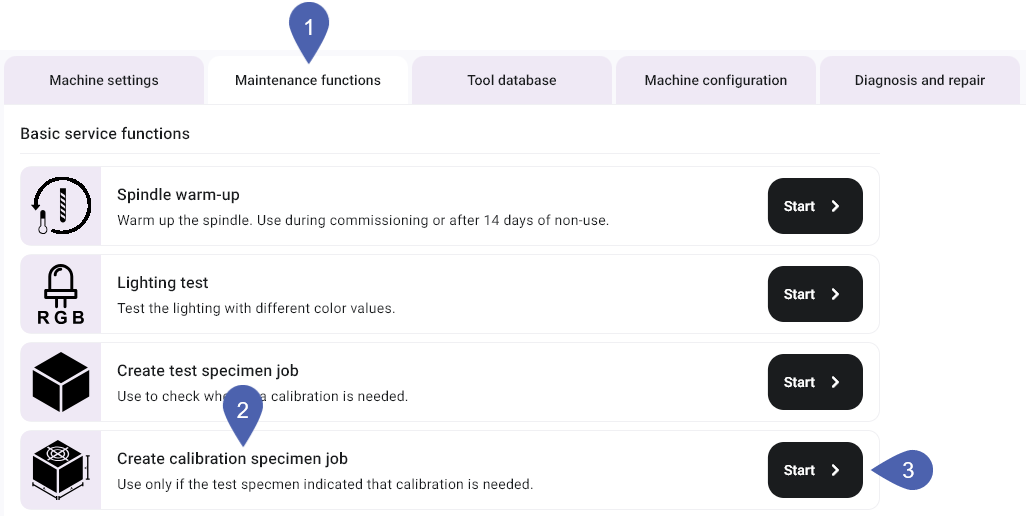
Open machine management with the following icon in the Main icon bar:

-
Select the Service functions tab.
-
In the Create calibration specimen job function, select the Start button.
-
dentalcnc adds the job to the queue.
-
Open the Manufacturing view with the following icon in the Main icon bar:

-
Manufacture the job like any other job.
-
The window for entering the measuring values opens.
-
Remove the calibration specimen from the machine.
- E3
- E4
- E5
- K5, K5+, S5, S5m
- N4+
- R5
-
Remove the calibration specimen from the machine.
-
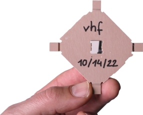
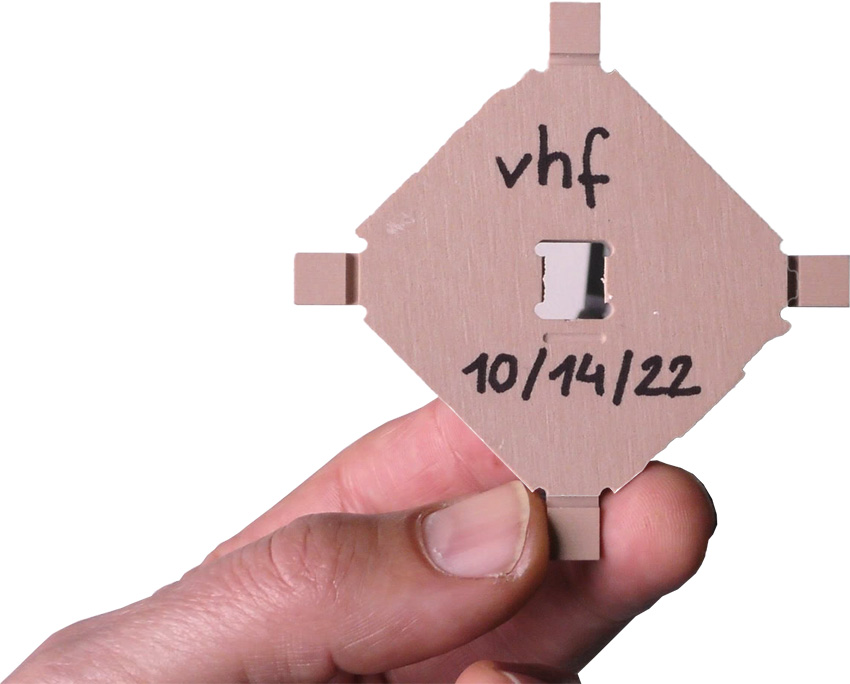
Recommendation: Label the calibration specimen with a name and date.
-
To ensure accurate measurement results, remove all manufacturing residues with a brush.
-
Recommendation Put the individual parts onto a flat surface so that you can use both hands to handle the micrometer.
-
Measure the calibration specimen.
- Measure each position 2 times.
-
Record all measuring values.
-
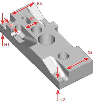
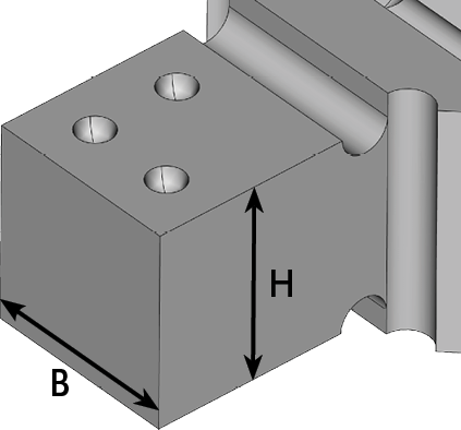
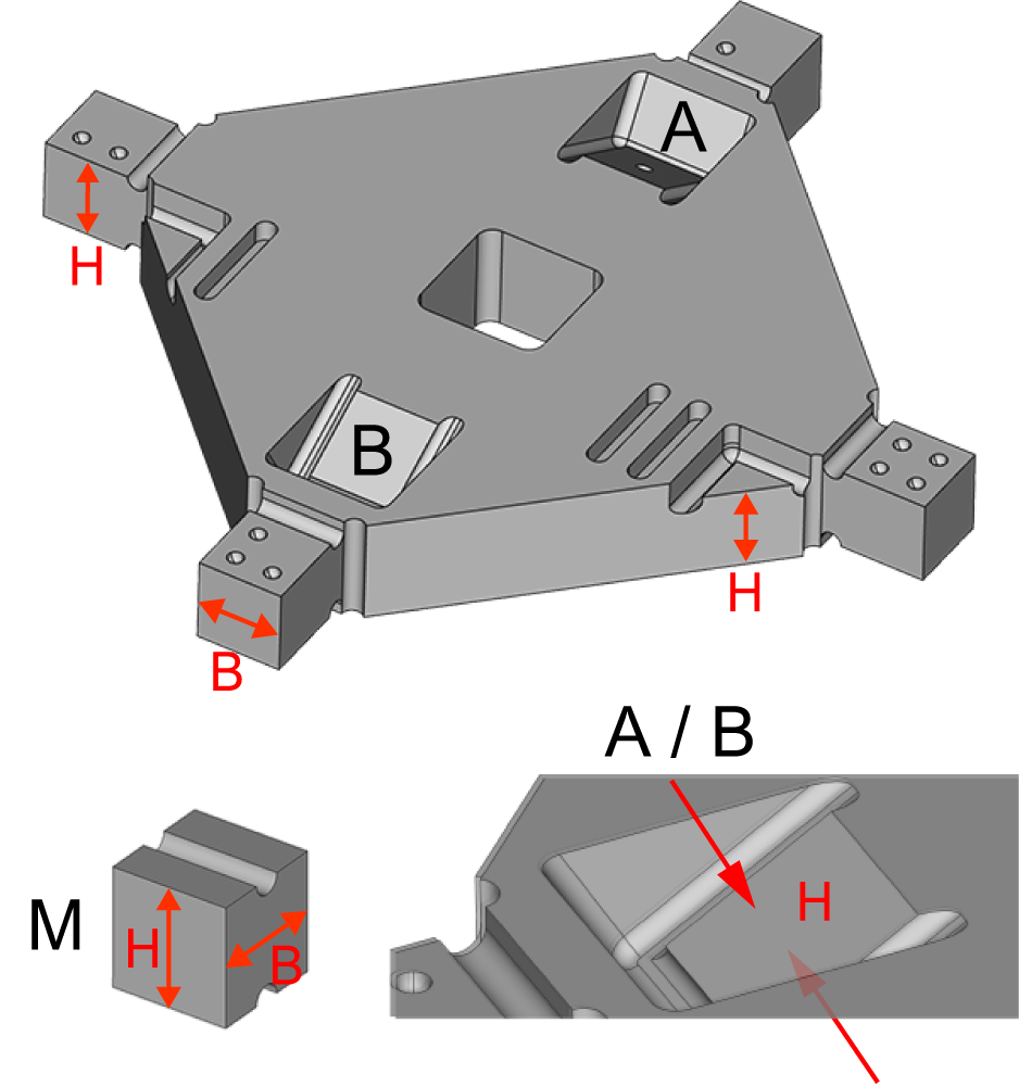
Measure the height of the measurement points that begin with H.
Number of measurement points: 2
-
Measure the width of the measurement points that begin with B.
Number of measurement points: 4
-
Remove the calibration specimen from the machine.
-
Recommendation: Label the calibration specimen with a name and date.
-
To ensure accurate measurement results, remove all manufacturing residues with a brush.
-
Recommendation Put the individual parts onto a flat surface so that you can use both hands to handle the micrometer.
-
Measure the calibration specimen.
- Measure each position 2 times.
-
Record all measuring values.
-
Remove the calibration specimen from the machine.
-
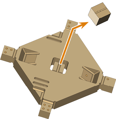
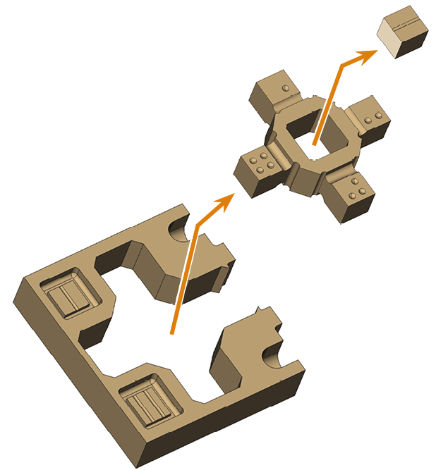
Separate the parts.
-
Recommendation: Label the calibration specimen with a name and date.
-
To ensure accurate measurement results, remove all manufacturing residues with a brush.
-
Recommendation Put the individual parts onto a flat surface so that you can use both hands to handle the micrometer.
-
Measure the calibration specimen.
- Measure each position 2 times.
-
Record all measuring values.
-
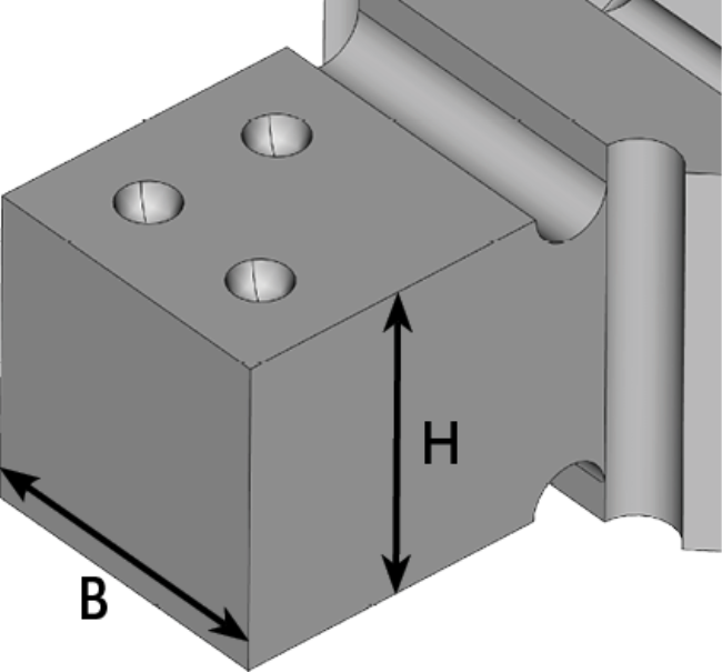
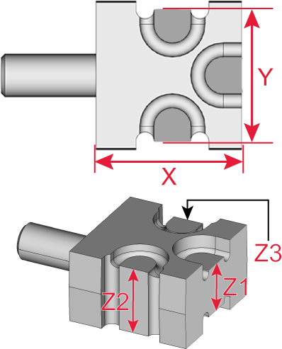
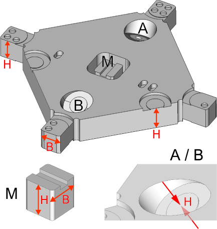
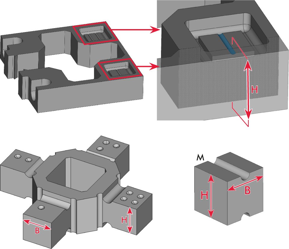
Measure the width and height of the measurement points, which are marked with circles.
Number of measurement points: 4
-
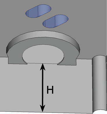
Measure the heights of the surfaces marked with bars.
Number of measurement points: 2
-
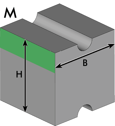
Measure the width and the height of the cube M.
- Measure the height and width as shown in the following figure.
-
When measuring the width, place the micrometer at the top of the cube (area marked in green).
-
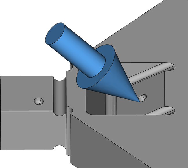
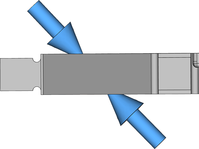
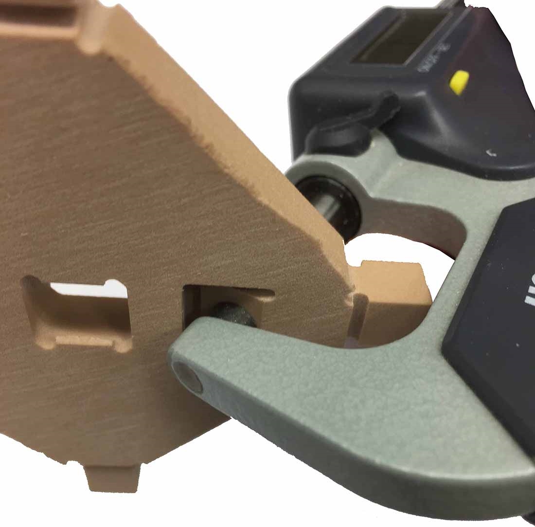
If a new end switch or ball screw drive has been installed on the X-axis, measure the distance between the opposing inclined surfaces.
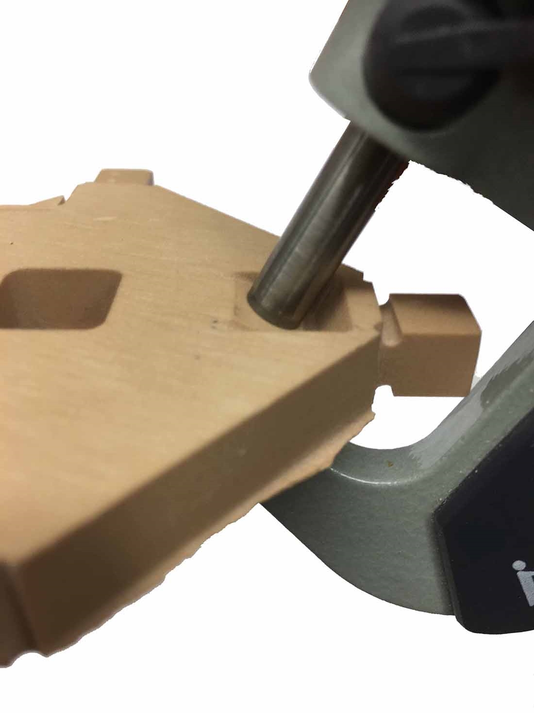
Place the measuring spindle on the top of the calibration specimen.
Number of measurement points: 2
-
Inclined surface A is marked with a point on the top of the calibration specimen.
-
Inclined surface B is not marked.
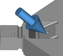
Inclined surface A
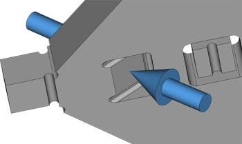
Inclined surface B
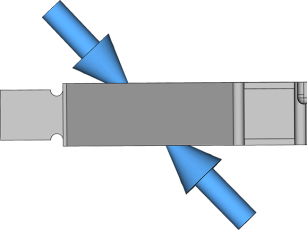
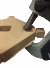
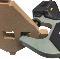
Measuring the slanted surfaces with a micrometer
-
-
Remove the calibration specimen from the machine.
-
Separate the parts.
-
Recommendation: Label the calibration specimen with a name and date.
-
To ensure accurate measurement results, remove all manufacturing residues with a brush.
-
Recommendation Put the individual parts onto a flat surface so that you can use both hands to handle the micrometer.
-
Measure the calibration specimen.
- Measure each position 2 times.
-
Record all measuring values.
-
Measure the width and height of the measurement points, which are marked with circles.
Number of measurement points: 4
-
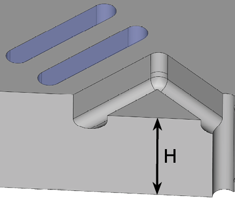
Measure the heights of the surfaces marked with bars.
Number of measurement points: 2
-
Measure the width and the height of the cube M.
- Measure the height and width as shown in the following figure.
-
When measuring the width, place the micrometer at the top of the cube (area marked in green).
-
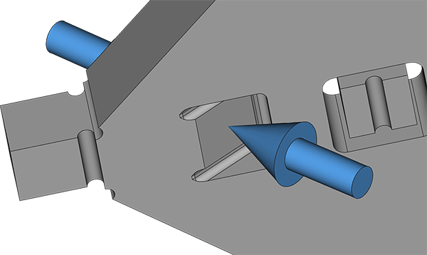
If a new end switch or ball screw drive has been installed for the Y-axis, measure the distance between the opposing inclined surfaces.
Place the measuring spindle on the top of the calibration specimen.
Number of measurement points: 2
-
Inclined surface A is marked with a point on the top of the calibration specimen.
-
Inclined surface B is not marked.
Inclined surface A
Inclined surface B
Measuring the slanted surfaces with a micrometer
-
-
Remove the calibration specimen from the machine.
-
Separate the parts.
-
Recommendation: Label the calibration specimen with a name and date.
-
To ensure accurate measurement results, remove all manufacturing residues with a brush.
-
Recommendation Put the individual parts onto a flat surface so that you can use both hands to handle the micrometer.
-
Measure the calibration specimen.
- Measure each position 2 times.
-
Record all measuring values.
-
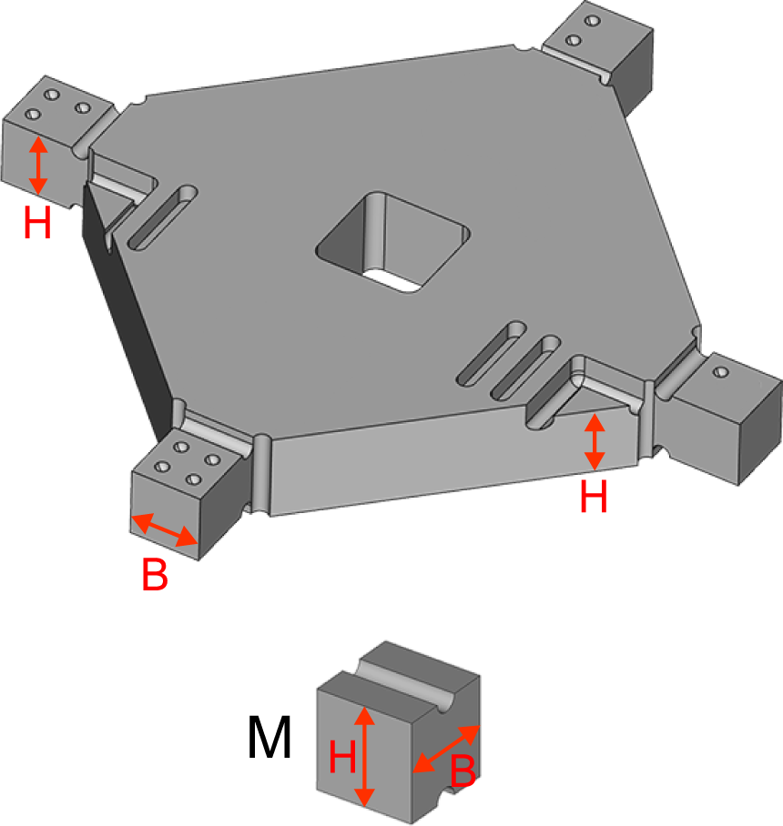
Measure the heights of the surfaces marked with bars.
Number of measurement points: 2
-
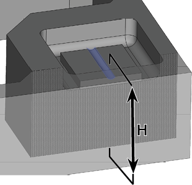
Measure the height of the inner blocks marked with bars.
Number of measurement points: 2
-
Measure the width and the height of the cube M.
- Measure the height and width as shown in the following figure.
-
When measuring the width, place the micrometer at the top of the cube (area marked in green).
-
Remove the calibration specimen from the machine.
-
Separate the parts.
-
Recommendation: Label the calibration specimen with a name and date.
-
To ensure accurate measurement results, remove all manufacturing residues with a brush.
-
Recommendation Put the individual parts onto a flat surface so that you can use both hands to handle the micrometer.
-
Measure the calibration specimen.
- Measure each position 2 times.
-
Record all measuring values.
-
Measure the width and height of the measurement points, which are marked with circles.
Number of measurement points: 4
-
Measure the heights of the surfaces marked with bars.
Number of measurement points: 2
-
Measure the width and the height of the cube M.
- Measure the height and width as shown in the following figure.
-
When measuring the width, place the micrometer at the top of the cube (area marked in green).
-
Enter the measuring values of the calibration specimen in dentalcnc.
-
Use the graphic displayed to identify the correct input fields for the measurement fields.
-
Check each entry before saving.
-
-
Select OK.
-
dentalcnc calculates the new calibration based on the entered values and applies it immediately.
-
Check the success of the calibration by manufacturing and measuring a test specimen.
Example:
Example:
Example:
ATTENTION! Incorrect measuring values due to an error in measuring the M cube
Example:
ATTENTION! Incorrect measuring values due to an error in measuring the M cube
Example:
ATTENTION! Incorrect measuring values due to an error in measuring the M cube
Example:
ATTENTION! Incorrect measuring values due to an error in measuring the M cube
ATTENTION! Incorrect calibration due to the entry of measuring values of a test specimen


